
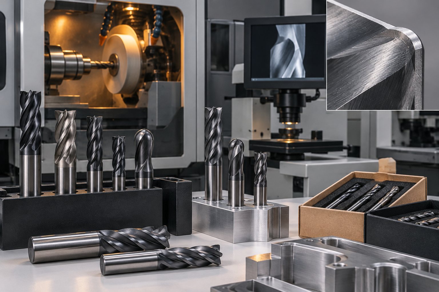
What the radius changes
On a square tool, the corner between periphery and face is the thinnest, most exposed part of the cutting edge, and in shoulder work it takes the full load at a single point. Put a radius there and the geometry changes character: the load spreads along an arc, the edge resists chipping, and on harder materials the tool holds its cutting geometry longer. That is the whole commercial argument for the family, and it is why bull noses have become a default answer on alloy steels, stainless and titanium work where a sharp corner would wear or chip first. Nothing else about the tool is exotic - flutes, helix, substrate and coating follow the same rules as the rest of the catalog. The radius is the feature.
Where buyers spec it
Three triggers bring bull noses into a program. Material first: harder alloys punish a point-loaded corner, so a radius buys margin exactly where the tool needs it - the material pages on steel and titanium set that context. The print is the second trigger: many drawings already carry a corner radius allowance at internal corners, and a bull nose cuts that radius directly in one pass instead of leaving it to a second operation or an acceptance argument. Strategy is the third: a radiused corner takes heavy passes with less corner wear, so some programs run bull noses for roughing and bring a square tool in only where the print truly demands a sharp 90-degree corner.
| Tool | Corner geometry | What it leaves in the part |
|---|---|---|
| Square end mill | Sharp 90 degrees | Sharp internal corners; the mating geometry where a print demands them |
| Bull nose / corner radius (this page) | Radius per spec sheet | A radius equal to the tool radius in every internal corner it cuts |
| Corner rounding end mill | Full-radius form profile | Fillets and rounded edges - a form tool, not a shoulder cutter |
Choosing the radius value
The radius is a spec-sheet line, and the buyer owns the choice. A smaller radius protects the corner less but intrudes less on the part; a larger radius spreads the load further but leaves a bigger radius in every corner it touches and removes more floor material at the walls. The practical filter is the print: the tool radius must fit the smallest corner allowance your parts carry, and once it does, bigger is generally safer at the edge. Values are confirmed on the spec sheet per program - if your drawing names a radius, the tool carries exactly that value, measured optically at inspection. The desk does not infer a radius from a diameter; the two are separate lines on the radius benefits note as well.
Flutes, helix, substrate and coating
The same rules that govern square tools govern bull noses. Four flutes suit steel and finishing; three flutes are the aluminum compromise; two give chip room in soft materials and slots. Around 30 degrees of helix is the general-purpose default, with high-helix variants where aluminum needs better shearing. Fine-grain tungsten carbide is the standard substrate, with HSS and HSS-Co where toughness and economy lead. Coatings run TiAlN family for steels and dry machining, TiN for general purpose, polished uncoated flutes for aluminum, diamond family for abrasive non-ferrous and composites. Every one of those lines is confirmed per program rather than assumed - the trade-offs live in the flute count guide and the coating notes under carbide end mills.
Bull nose or square: the buyer's checklist
The decision reduces to three questions. Does the print allow a radius at the internal corners? Does the material - and your history of chipped corners on it - reward a stronger edge? And does the program have a finishing pass that can pick up the corners a radius tool leaves behind? Two yes-or-quietly-yes answers usually mean the bull nose wins; a print full of sharp internal corners means the square tool stays, with the wear implications priced in. The head-to-head is worked through in the bullnose vs square note.
Standard route or ground to your drawing
Standard bull noses follow reference radius values in the common diameter range and ship boxed, commonly ten pieces per box. The OEM route grinds the radius your range needs - a value the catalog does not carry, a long reach, your logo on the shank. Standard geometry with your mark starts from about 50 to 100 pieces per specification; special profiles are quoted per tool family against a drawing. Custom grinding samples take about 15 to 25 days after the drawing is agreed, bulk about 30 to 45 days after approval, coating adding a few days - typical reference ranges, confirmed in writing per program on MOQ and lead time.
What the desk checks before bulk
The radius is the headline inspection line: optical profile measurement against the value on the sheet, alongside diameter, flute geometry and runout at the cutting edge, then coating appearance, marking and packing. A certificate of conformance and material certificates travel with the shipment per program. The full checklist is on the quality control page - the desk's role is that the radius you approved is the radius that arrives.
Send the sheet
If your range runs corner radius tools, send diameter, radius value, flutes, length of cut, shank, substrate, coating and quantity per line through the quote form. A sheet in that shape quotes to the digit; a conversation about "a good corner radius cutter" does not.