
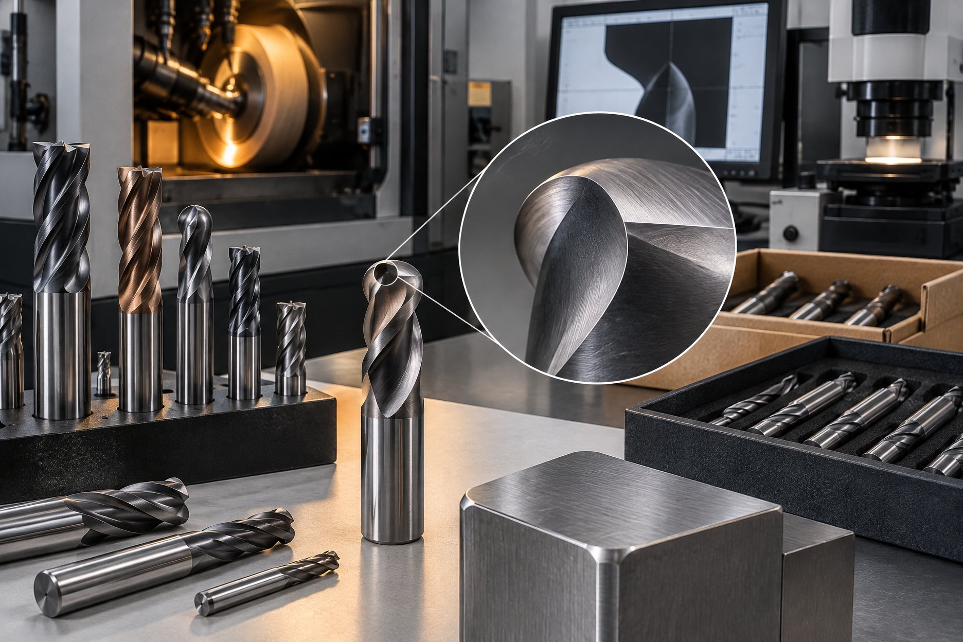
Edges, fillets, and the tool that is sized by the radius
Most drawings carry small radii somewhere: a fillet at the bottom of a pocket, a rounded edge on a part that hands will touch, a break that keeps a corner from chipping or a burr from forming. A square end mill cannot cut those shapes - its corner is a point. A ball nose can approximate a fillet, but only along a computed path, and the result inherits every error in that path. A corner rounding end mill is different in kind: it is a full-radius form tool, the radius is ground into the cutter as a fixed shape, and the fillet it leaves matches that shape directly. The radius is not something the machine calculates; it is something the tool is.
That is why the radius - not the diameter - is the primary line on the spec sheet. You choose the radius the drawing names, and the cutting diameter follows from the form: on a standard full-radius form tool the diameter is built around the radius rather than chosen independently. The exact pairing of radius to diameter, and the tolerance held on the form, are confirmed per spec - they are the two lines a buyer checks first when comparing quotes, because they decide whether the parts will pass inspection.
Where the tool earns its place
Three jobs dominate. First, internal fillets: the rounded corner at the bottom of a pocket or shoulder, where the drawing calls a radius and nothing else will pass. Second, edge radiusing: breaking the sharp edge of an external contour with a small radius instead of leaving it square or chamfering it. Third, form matching: parts that mate against a cast or molded radius, and wear parts where a rounded edge resists chipping in service. In all three, the form tool turns a geometry problem into a tool choice - and a measurable one, which is what an inspector needs.
Edge breaking deserves a note, because it is where the family overlaps with chamfer work. A chamfer leaves a flat bevel at 45 degrees; a radius leaves a curve. For parts that are handled, coated, anodized or assembled into plastic housings, the radius is usually what the drawing asks for, and the chamfer mill handles the rest of the edge-prep list. Many shops carry both and split the edges between them.
Corner rounding, bull nose and ball nose: not interchangeable
Buyers mix these three up, and the mixup costs reorders. All three have a radius somewhere, but they are specified and used differently, and quoting one where the program needs the other shows up at inspection.
| Tool | What the radius is | How it is sized | Typical work |
|---|---|---|---|
| Bull nose | Radius at the corner between periphery and face | By diameter; the radius is a smaller attribute | Longer-life milling of walls and floors |
| Ball nose | Full hemisphere at the tip | By diameter, run on computed 3D paths | Contours, molds, curved surfaces |
| Corner rounding | The full form of the nose | By radius; the diameter follows the form | Fillets and edge radiusing to a named R |
The practical test: if the drawing names a radius the part must measure, you are in form-tool territory and the corner rounding end mill is the family to quote. If the radius is only there to protect the cutter's own corner, a bull nose does that job while cutting flat walls with a larger diameter. The trade-offs between the two are laid out in the corner radius note.
Form, neck and reach
Because the nose carries the form, the body above it is usually ground to a neck narrower than the form diameter - clearance that lets the full radius sweep past a shoulder or into a pocket corner without the shank rubbing. Neck length is therefore a spec line in its own right: it decides how far into a feature the tool can reach before the neck or shank interferes. Stub forms hold rigidity; longer necks reach deeper but give up stiffness. What the catalog carries and what is ground to order are both routes on this desk.
Flutes, helix and coating follow the material, not the form. Two- and three-flute ground forms are common where chip room leads, four where finish leads; the trade-offs are the ones described in the flute count guide. Steels and stainless usually run the TiAlN family, aluminum an uncoated polished form to resist built-up edge, and abrasive composites the diamond family. The aluminum page carries the material-side detail; the same coating logic applies line by line.
What the spec sheet names
| Radius (R) | The primary line; the fillet the tool leaves |
|---|---|
| Cutting diameter | Follows the form; pairing confirmed per spec |
| Neck diameter / length | Clearance above the form; decides reach |
| Shank | Plain cylinder the holder grips |
| Flutes / helix | Per material; guide linked above |
| Coating | TiAlN family, TiN, uncoated polished, diamond family |
| Form tolerance | Held on the radius; confirmed per spec |
Standard radii or ground to your drawing
The common radius range is standard catalog territory: ground to reference geometry, boxed - often ten pieces per box - and quoted per line item. Programs that need a radius the catalog does not carry, an inch-metric pairing, or a tolerance tighter than reference go the OEM route: your drawing, ground to it, your logo laser-marked on the shank. Custom grinding samples take about 15 to 25 days after the drawing is agreed, bulk about 30 to 45 days after approval, and every figure is confirmed in writing per program - the reference table lives on the MOQ and lead time page. If you have a list of radii and quantities, send it with the quote form; the desk quotes from the sheet, and the sheet starts from your drawing.