
The tool shaped like the joint
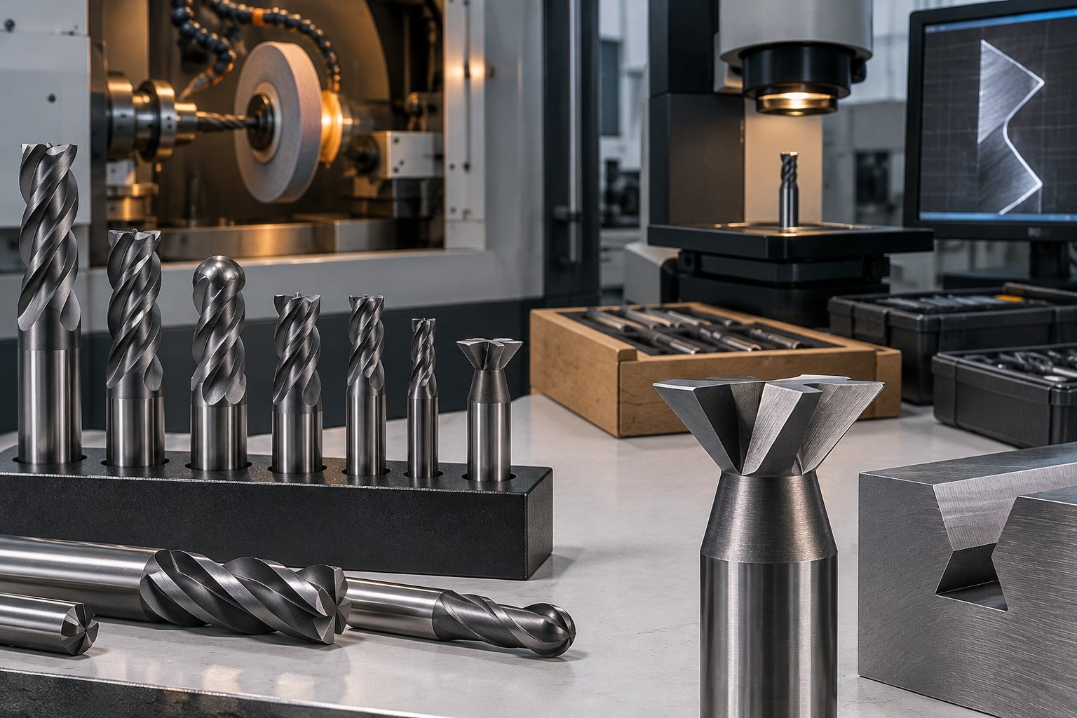
A dovetail is an undercut by design: two angled flanks that widen toward the bottom, so whatever slides into the slot cannot pull out perpendicular. Cutting that shape needs a tool built inside-out compared with an end mill - an inverted cone. The cutting edges sit on the angled face at the tool's tip, the widest point of the cutter; above them the body narrows so it can reach down into the slot and sweep the flanks. The angle of that face is the specification: 45 degrees and 60 degrees are the common included angles, confirmed per spec, and the tool's angle must match the drawing's angle, because no path can turn a 45 into a 60.
Where dovetails get cut
Workholding is the engine of this family. Dovetail fixtures and jaws grip parts around a dovetail-shaped tongue, holding stock for five-axis and second-operation work with the gripping force pulling down into the fixture rather than squeezing the sides - a format that leaves most of the part exposed to the cutter. Every such fixture and every set of soft jaws is cut with a dovetail cutter, usually by the shop that will use it. Beyond workholding: slide ways and machine components where the dovetail is the guide, fixture plates and clamp features, and part features themselves - a dovetail is a mechanical joint as well as a gripping format, and both appear in job shop work.
Why workholding adopted the dovetail
The dovetail's gripping logic explains its spread in modern workholding. A vise squeezes two faces; a dovetail fixture pulls the part down and into the pocket, so cutting forces seat the part rather than lift it, and the exposed stock above the grip line is cut all around without rechucking. For five-axis work, where the part rotates while held, that difference is structural, not cosmetic. The consequence for this tool family is volume: every fixture plate and jaw set in that format is a dovetail cutting job, and shops that adopted the format keep a dovetail cutter for each angle and size they run. It is one of the quiet self-sustaining categories in tooling - the tool makes the fixture, and the fixture calls for the tool again.
Single angle, double angle
Two forms cover the family. A single-angle cutter cuts one flank and leaves the other to a second pass or a second tool; a double-angle cutter forms both flanks of the dovetail in one profile. Which one fits depends on the feature and the access - a shoulder beside the slot may allow only one cutting flank at a time. The included angle on each form is the primary line, with the width of cut at the tip and the resulting large diameter following it, all confirmed per spec sheet.
Geometry lines that define the cut
| Line | What it decides |
|---|---|
| Included angle | The dovetail's flank angle - commonly 45 or 60 degrees |
| Tip / cutting width | The narrow width the tool enters the slot by |
| Large diameter | The widest reach of the flanks |
| Length of cut | How deep the angled form reaches |
| Shank / OAL | Holder fit and total reach |
The angle is ground into the form, so it is quoted and inspected as a form feature, not produced by the path - the same logic that governs corner rounding forms, and the reason a dovetail program is quoted from the drawing's angle line first.
The undercut rules apply here too
Dovetail cutting shares the T-slot cutter's honesty: the blade works under a shoulder and the chips must leave through the slot it entered by. Shallow passes, withdrawal to clear, and rigid holders are the practical baseline - runout at the cutting edge and a compliant setup turn the angled cut into chatter quickly. The holder page covers the fit side; the parameter side follows the standard starting-point math on the speeds and feeds page, adjusted to the machine and setup; and when chatter does appear, the usual fixes are cataloged in the chatter note.
Substrate, coating, and materials
Most dovetail work lands in aluminum, mild steel and tool plate - fixture materials - so both HSS-Co and solid carbide have real places: HSS-Co where shock and hand work dominate, carbide where stiffness and finish lead. Coating follows the material: the TiAlN family for steels, uncoated polished where aluminum leads. All substrate and coating lines are confirmed per program, as with any spec sheet, and the material-side trade-offs are covered on the HSS page and the aluminum page.
What inspection looks at
Because the angle is a form feature, acceptance is measured on the form: optical profile measurement of the included angle and the tip width, runout at the cutting edge, and the surface condition of the flanks. A small deviation on the angle is invisible on a label and obvious in a mating fixture, which is why the inspection plan for dovetail programs checks the form against the approved sample rather than against the catalog description. Marking and packing close the checklist - neutral or your logo on the shank, boxes labeled with the angle line. The general process is described on the quality control page.
Standard angles or your drawing
The common angles and widths are standard catalog items: boxed, quoted per line item, shipped in days. Fixture builders and machine builders who need a non-standard angle, a width between standards, or their own marking on the shank go the OEM route - your drawing, ground to it, samples about 15 to 25 days after the drawing is agreed, bulk about 30 to 45 days after approval, quantities from around 50 to 100 pieces per specification. Reference figures, confirmed in writing per program; the table is on the MOQ and lead time page. Send the angle, width and quantity with the quote form and the desk returns the route and the spec sheet.