
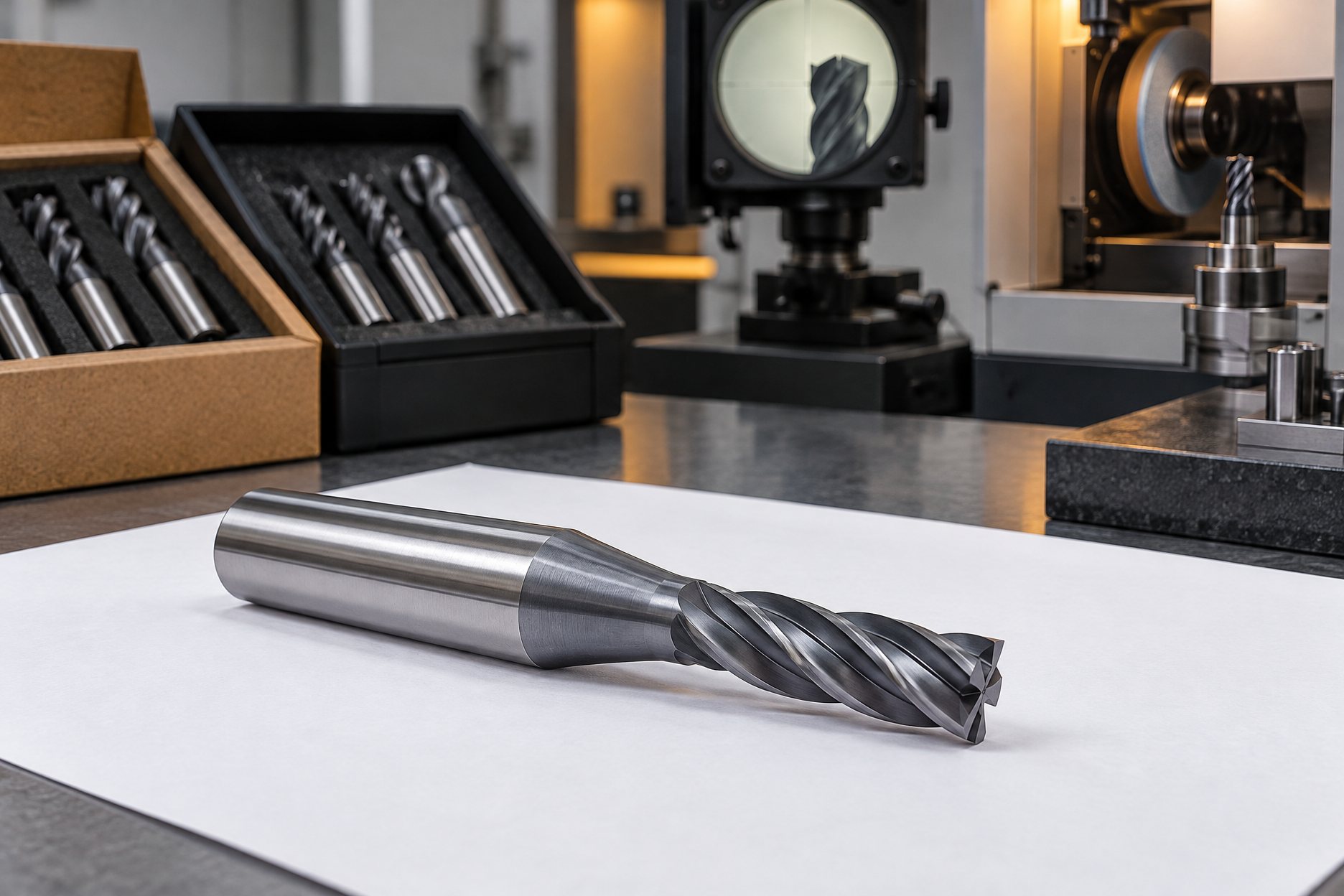
What the taper does
Replace the straight body of a standard end mill with a cone and two things follow. First, the tip is supported by a body that grows thicker behind it, so the tool carries a cut at depth with more backbone than a slim straight tool of the same tip diameter can offer - reach stops being the weak point quite so quickly. Second, the flanks cut a taper: any wall machined along the cone comes out at exactly the angle ground into it. Both behaviors are why the family exists. Draft angles and mold walls need an angle held faithfully over a deep wall; engraving and deep cavity work need a tip that reaches where a fat straight tool cannot fit. The taper angle itself is a spec-sheet line - degrees, confirmed per program - and the tip carries the cutting geometry: flat, ball nose or corner radius, per drawing.
Draft angles and why molds need them
Draft is the slight angle built into the walls of a molded part so the part releases from the tool instead of gripping it. Too little draft and every cycle fights the wall; the same logic applies on the mold side, where cavities and cores are cut with matching tapers. A tapered end mill lets the shop cut that angle directly: pick the tool whose angle matches the print, and the wall comes out right along its whole depth in one pass. That is neater than approximating a taper with stepped straight-wall passes and blending them afterward. Mold and die work in general - where tapers, ball geometry and deep reaches meet - is walked through in the mold and die note.
Ball taper for engraving and deep cavities
Put a ball nose tip on a tapered body and the tool gains a third talent. The ball reaches the bottom of a tapered wall smoothly; the cone behind it keeps the tool stiff at depths where a straight ball nose would be all whip. That combination - a taper with ball nose - is the standard answer for engraving work and for deep, tapered cavity walls, and it is why the ball taper is the single most requested variant in this family. The angle-specific details, including how angles are read and specified, are in the taper angles note; the ball geometry itself is covered under ball nose end mills.
Tip options on a tapered body
The cone is the body; the tip decides the cut. A flat-tipped taper mills straight-flanked tapered walls and draft surfaces to a defined floor edge. A ball-tipped taper runs engraving profiles, fillets and tapered walls that blend into a floor. A corner-radius-tipped taper splits the difference where the print gives a radius allowance. Which tip a program carries is a drawing line, not a guess - and for non-standard geometry the drawing is required, because the taper, tip form and reach together define the tool.
| Line | What it tells you |
|---|---|
| Taper angle | The cone angle in degrees; state whether it reads per side or as an included angle - both conventions exist, and the sheet should say which |
| Tip form | Flat, ball nose or corner radius; defines the cut at the small end |
| Tip diameter | The small end; with the angle, it fixes the diameter at any depth |
| LOC / OAL / Shank | Length of cut along the cone, overall length, shank diameter |
| Substrate / coating | Fine-grain carbide standard; TiAlN family for steels, polished uncoated for aluminum |
| Marking | Neutral or your logo, laser marked on the shank |
Specifying the angle
Two conventions are in circulation - the angle per side and the included angle - so a taper program starts by saying which one the drawing means. From there the sheet carries the angle value, tip form, tip diameter, reach and substrate and coating choices. Standard reference tapers exist in the catalog range; the exact values available are confirmed on the spec sheet per program rather than quoted from memory. Anything outside the references is OEM territory: quoted per tool family, drawing required. The path from drawing to sample is described under custom end mill grinding, and the sheet conventions in the spec sheet template note.
Standard route or ground to your drawing
Standard tapered end mills in the reference angles and diameters ship boxed, commonly ten pieces per box, and suit mold shops and resellers filling a range. The OEM route is where most taper programs land eventually: an angle the catalog does not carry, a longer reach, a special tip, your logo on the shank. Quantities are quoted per tool family - tapers are the family where the per-specification minimum of about 50 to 100 pieces meets the reality of special geometry, so the figure is confirmed per program in writing. Sampling for ground-to-order tools takes about 15 to 25 days after the drawing is agreed; bulk about 30 to 45 days after approval, with coating adding a few days. The reference table sits on MOQ and lead time.
What the desk checks before bulk
Taper programs live or die on the angle, so inspection leads with it: optical profile measurement of the cone angle and tip form against the sheet, then diameter lines, runout at the cutting edge, coating appearance, marking and packing. A certificate of conformance and material certificates travel with the shipment per program. The checklist is on the quality control page.
Send the drawing
Taper requests quote best as a drawing: angle and convention, tip form and tip diameter, reach, shank, substrate, coating, quantity. Send it through the quote form and the reply names the route, the sampling plan and any lines still to confirm - in writing.